Rating
- Difficulty of Project:Easy
- Cost: $60 USD
- Recommendation skill level: Beginner
- Time commitment: Depends on skill level, assume at least 1 day.
Skills and supplies
- Desktop or laptop Computer with administrative access
- The Kit
The tutorial and instructions that I followed are by Keyestudio
From the Beginning
I bought the Inland branded kit from Microcenter. However, I'm pretty sure this kit is made by a totally different company, and just rebranded by Inland, given the links it gives all point to instructions by a company called Keyestudio, but they do have a full Wiki page with instructions and tutorials.
If you aren't near a Microcenter or want to shop elsewhere, the kit is available on amazon, but you can search for “IOT Smart Home kit keyestudio” and I'm sure you can find other retailers.
I'll be going through the whole wiki process from the start, which is actually learning how to use the arduino to turn a light on. One thing I think this kit does well, is it assumes no prior knowledge, so if you've never used an arduino before (This is only my second time trying one, first had ALOT of trial and error, followed by error, error error..) it's ok, the kit is designed to help. That's one of the reasons I picked it.
Let's get started
The first thing we need to do is install the Arduino IDE. The Wiki with instructions does have a tutorial on how to install the Arduino IDE which I will recommend to you because it explains how to install it on a Windows machine, I use Linux so my install process is unlikely to look like yours. In good news, the Arduino IDE install was very easy even on Linux, and literally the first step after that is plug in your board, and the kit even comes with a USB cord.
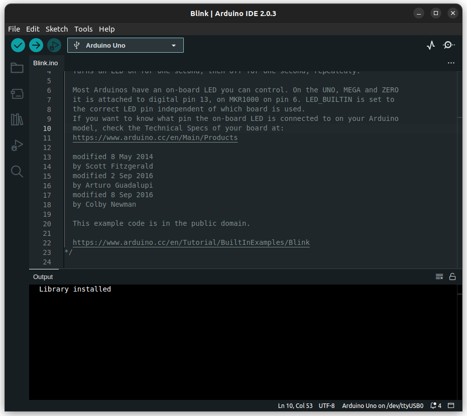
The next step in the tutorial is making sure that your board is connected, and trying one of the example programs, in this case it's just called "Blink". This will allow you to practice making sure your board is showing up correctly, you can send a program to your board, and that you are comfortable with the workflow on the Arduino. The tutorial says you'll see "COM" on the port, I did not, I saw "Dev Uno on /dev/ttyUSB0" now this could be because I'm using Linux, this could be because I'm using the Arduino IDE v2.0.3 instead of "v1.8.12" that is being used in the tutorial. The IDE does get updated very frequently, so I'm not surprised my version is newer, but it's worth mentioning just in case. The Official Documentation for the Built-In examples is also a place you can look if you want to see another example of how to do the Blink Tutorial.
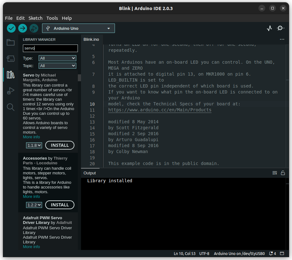
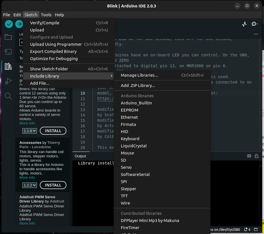
Next Step is adding in libraries. In good news, this is pretty straightforward, and there are lots of examples for this. The Wiki with instructions does have a walk through on how to add a library. The Official Arduino documentation also has instructions for how to add a library. However, I would like to note here, there are more then one way to include a library, the library manager that looks like this:
Projects 1 & 2
Now that the libraries are installed, we can continue with the LED blinking light. Our first project is going to be getting an LED blinking, the instructions for Project 1 are going to include some wiring, so our first steps are going to be getting our boards setup following the images. The basic idea is that we are going to need to take the Sensor Shield, attach it to the Arduino, and then add on the white LED module to the shield. There are more instructions and pictures on the tutorial.
Couple of things I noticed as I was working, if you are already comfortable with electronics you can probably skip this part. First, it says "attach the shield" but it doesn't say how or where. I put the shield on so that all the pins are touching, but as far away from the USB as it can go. Next, when you attach the shield, or do the wire connection, it take a surprising amount of force to get everything together, I would say delicate but firm force is needed. Support the pins with your finger as you're attaching the wire, and make sure it "clicks" in as you're working, otherwise it'll just fall out and get lost/eaten by dogs. Lastly, look at the colours of the wire, conventionally the black coloured wire is the Ground, so consider practicing with that and make sure the black colour is attached to the "G" on both the light board and the sensor shield. There are only two boards in the accessories box with LED lights that I could find, one was yellow one was white, we're starting with the white one.
After you have everything wired, you'll take a copy of their code, paste it into your Arduino IDE, then click the check, then the arrow (Verify, then Upload) and if everything worked you'll have a white LED light up. If you're not comfortable with code, make sure to carefully read the explanation so that you can follow what's going on. One thing that i experimented with was combining the code so I can see what's going on and what's changing between the two LED lights and how they are different.
Project two is similar, except it's a yellow LED and it has a power change to make it look like it's breathing instead of just turning on and off. One thing you can try to make sure you understand the code is to combine projects 1 and 2, can you make both lights turn on? Can you have one with the power change and one that just turns on and off? Can you switch which one is which? My code that I was playing with is here.
Projects 3 & 4
Buzzer from Project 3, yikes loud. You have been warned.
There was an error in the code for Project 4, easy fix though. When you are coding there is a concept of comments, things in your code that are like notes to yourself or others, these don't get run/compiled/seen by the computer, it's just a way to say things like who made the program, what it's used for, things like that. There was an issue with how the comments were structured, make sure there is no space between the / and the *
/*This is a comment that is valid for Arduino code*/
/ * this is not
Next I started trying to modify the code so that I can have the white LED and yellow LED light up on button press so I can practice how everything works. The practice code for Project 4 where I made the updates to include a second LED light to turn on and get rid of the error from the comments. You can see the changes that were made compared to the original project 4 are minimal, but it's good practice to make sure I understand how everything is put together. You can try playing with my code, can you change which pins each light or the button uses? Could you make the light brighter or dimmer?
Projects 5 & 6
For Project 5 we're starting to get a little more complex. You will need to take some of the individual wires and hook them up instead of the set with 3, you'll also need to use two kinds of wires. They did say which ones to use, but it was a little unclear what they meant since I'm not really super familiar with electrical terminology. The male to female means the cable with one pin, the female to female is the cable with no pins. Another thing to note is that when you plug the pin into the relay it does a bit of a soft click, and when you run the program there is a clear "click" that you can hear. Once you are done you'll see that it goes with the LED turning off or on.
For Project 6, the code doesn't do what it says it does. The wiki guide says the LED light will be on until a flashlight is used, however the LED light is actually OFF until a flashlight is used. However, the comments on the code don't match the wiki guide. The modified code is Here if you're interested. The light will be on until you use a flashlight, then it will turn off. The flashlight from my phone is enough to trigger this, but the screen from my phone is not. You can change how much light you need to trigger the LED going off by playing with the number in the if statement line here:
if (val <900)Try changing it lower and higher and see what happens.
Projects 7 & 8
Project 7 you'll be attaching one of the two servos. Now, they have switched the Ground connection, so instead of a black wire, it's the brown wire. Another note, the servo comes with 4 white plastic options that are supposed to attach to the little white knob on the top of the servo. Which one and how to attach isn't mentioned in the wiki. For my kit, I tried the fan with one blade, and it wouldn't attach. The one with two long and two short blades does attach by pressing it on. There are screws included, but I didn't want to use them because there didn't seem to be threads and I didn't want to break anything.
To ensure I understand how the code is working at this point I've made some modifications to my code, I've added in a simple light that turns on during one of the rotations, and off during the other. This allows me to both practice working with multiple pins, multiple input/output options, and seeing how the loop is put together. It's good I tried this, because the first edit had the on and off in same loop and that meant instead of turning on and off with the servo the light just took over, which isn't what I wanted. Can you add in another light? Maybe yellow LED in one direction, white LED for the other? Or try adding in one of the other projects you've tried so far to this code.
Project 8 this is going to use the fan, and will be more complicated then the previous projects. One thing that makes this more complex is that we have 4 wires instead of 3 that need to each be connected. They do have a note on how to do it with a picture, but it was a little confusing. I found connecting the wires one by one to be the best option, NOTE: these are going to be the female to female connector wires, the ones with ports on both sides, no pins welcome here. First I got a black wire and connected the G (Ground) on the fan to the G on the 6, VCC connects to V on the 6 pin, and INB connects to S on the 6 pin. The 7 pin S on the shield connects to the INA on the fan. Before running your code I suggest picking up the module and holding it away from yourself with the red fan part clear. It is surprisingly loud and fast. It really does generate a breeze my dogs did not appreciate in February in New England.
Projects 9 & 10
Project 9 There wasn't a great way for me to test this, because the house is attached to my laptop for programming and power, and I'm not carrying my laptop and the kit over to the stove with boiling water, I'm just going to assume everything works as intended.
Project 10 Is going to use the fan again, as well as an LED and the motion sensor. The wiring is the same as project 8 for the fan, and the LED was on pin set 13. If you want to try playing with the code, could you change the pin set for the LED? Or maybe try and add in another LED? You could even try adding the buzzer if you enjoy noise for whatever reason.
Projects 11 & 12
Project 11 This was easy to wire together, but I didn't really want to test it with flamable gas. So we're just going to assume it works fine, no fire required. Also I hate noise and can't stand the buzzer for even 30 seconds. I checked with my dogs and they agreed, no buzz buzz allowed in my house.
Project 12 Another nice and straightforward project. The LED screen plugs in nicely with the 4 port connector, there is a clear spot for it on the shield. And the code is clear and easy to use. Try changing what it says!
Projects 13 & 14
Project 13 Another nice straightforward project, easy wiring, works right away. I'm doing this in winter, so the air is in the value range of the 90s, which isn't unexpected.
Project 14 Bluetooth, you'll need their app or another bluetooth reader, the kit comes with the HM-10 Bluetooth module, which supports Bluetooth 4.0 on both Android and iOS. If you don't want to use your phone, you can use another option if you have one. In their wiki they do use older terminology which is up for debate on the change and there are even some style guides like this one from Microsoft suggesting that you use other terminology. There is a surprising about of offensive, and potentially offensive terms in technology (just look at the way we talk about cables, male/female, really people?) so it's worth considering the language you are using as you're writing up documentation, there are ways to be clear and not offensive. It's ok to not be perfect at it, no one is perfect, but consider how others might read/hear/see what you do, what you say and how you say it.
The code that is given is very simple, basically what will happen is that you need to connect your phone or laptop to the bluetooth module. The issue is that trying to do this without the app they tell you to use is difficult. So to get this working quickly and easily, you'll need to download the suggested app. I did not have any luck pairing the module with my laptop or phone without the app. The test is going to be pairing the app to the module, then when you hit the different buttons and sliders in the app, different letters appear in the serial monitor section of the Arduino IDE. 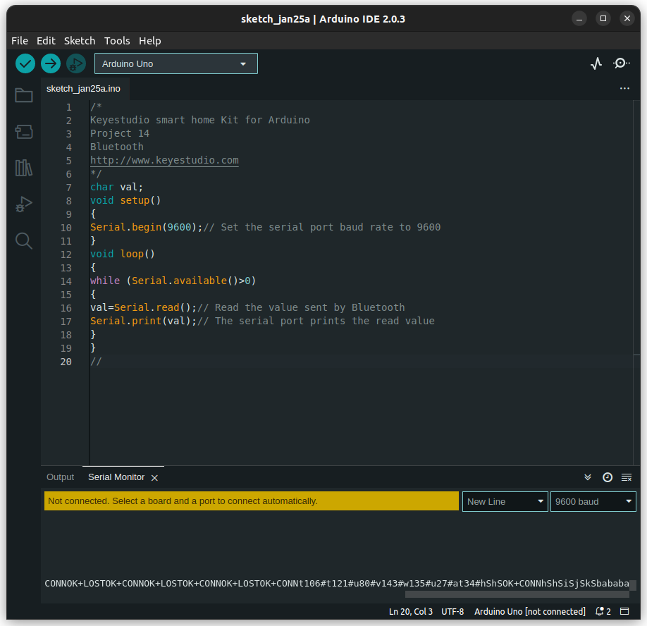
Putting it all together
Assembly guide There are several things I would like to make note of during the assembly process. Mostly it was things I found unclear as I was going through the guide, I also have a note on assembly order, it matters in some cases. For me personally, I can't stand the noise from the buzzer, so I edited their code to remove it, you can find the edited version here.
Note one: The M3 screws were not labeled correctly on my kit it was labeled M3 10 mm round head nuts 20 pieces and I believe they actually meant M3 10 mm round head screws there was also M3 nickel plated nuts 25 pieces so that's why I think it was mislabeled.
Note two: The instructions are relatively clear but getting the nut onto the screw was a little bit difficult. My solution was to 3D print a small wrench, I used this one from Thingiverse, but there are a bunch of options. If you don't have a 3D printer I would encourage you to check with your school, they might have one you can use, the print only took 15minutes, so it wasn't a big thing. I would also encourage you to try looking around your town/city for a makerspace, they might be willing to help. And lastly, try your library, some libraries have makerspaces and 3D printers. Plus libraries are awesome and librarians are the best.
Note three: On the board A1, you will be installing an LED. It is important to make sure that you are paying attention to orientation, otherwise your words will be upside down. The board when it is pushed through should have the pins that you connect to facing towards the small square hole on the board as pictured in the image. They did make sure to include a picture which was very helpful, but just make a note that you have to follow the picture exactly or you're board will be upside down.
Note Four: One of the things that you'll notice on their picture is that they were able to get the wires to very nicely connect. This was actually really difficult for me, and the thing that I found that you need to do is actually untwist the twisted wires. So they gave you a bunch of three pin connectors, the pin connectors do Match the black ground that you're used to from the rest of the tutorials and it is important to make sure that when you are plugging them in you're continuing to go with the color scheme of g is the black wire for ground. But if you would like them to sit nicely after you plug them in make sure that you untwist the three wires before trying to feed them through the holes and connect. If you leave them twisted they won't be able to connect nicely and you'll have these kind of ugly loops of wire on the front of your kit. I know that because the first time I tried this I did not untwist them and I had ugly loops of wire on the front of my kit.
Note five: When I was connecting the LED board one of the things that I noticed is that the four port option actually has black in a different place so on all of the other options the black wire is always going to be the ground. But it appears that the board that is coming off of the LED board is saying that it's ground then BCC then SDA then scl. And therefore the ground wire is actually red and the VCC wire is actually black. The color of the wires does not actually affect anything, you can have them all be the same color if you wanted to it really doesn't matter. The thing that does matter is that the pins match. So one of the things that you do have to note is whatever side you have on ground you have to make sure matches the ground wherever you're plugging in the other side of these wires.
Note six: Once you get to step five of assembly, they are going to have you do some screws with self-locking nuts. Self-locking nuts can come off, the reason that they're having you use the self-locking knots with the long screws is because the servo motor is going to be used in conjunction with the gear to make the same moving part. As you're putting this in you'll notice that part one is actually movable you'll notice that the screws will move and the nuts are not going to be tightly on the back the way it is for the rest of the project and that's fine don't worry about it
Note seven: On step 11 when you are connecting the sensors to the module it's very confusing to look at their grid. When they say corresponding installed area on the board they don't mean the corresponding pins, they are talking about the step that you did in the tutorial as we got down here. To figure out which set of pins they're talking about you have to look at the third column from the left. So for example, the white LED says G/V/S that's where it plugs in on the white LED board, you'll see next to that it says G/V/13 and then next to that it says one. The one is actually because that's the first tutorial that we did we are not plugging this in to pin set one. We're plugging this into pinset 13. If you scroll down there was some images to follow as well, and they did keep to the same pins as the tutorials, but it is worth being careful where you plug everything in, and which order everything is in.
Last note: The roof. Oh my goodness, putting this roof on was a bear. When you get to the point that you have to get the roof piece with the fan on it is important to both pay attention to which direction things are going and that there is a step in here which is not well explained. On part F there are two screw holes that are going to correspond to two small pieces on the extra board that are going to need to be screwed in. This isn't particularly mentioned other than in a single image, and there's also no indication at what point the piece should be mounted given that there is an entire slot of options I assume for extra space to fit in. But it is important to know that you do need to add those in before you can fully mount the house together Order matters on the roof! I would recommend getting piece F and E both put together and attached before trying to put on the rest of the house. The reason being that you're going to need to have the space to get your hands in there to do the attaching and G is just going to be a cover-up. The F part of the roof was absolutely awful to get on. The way that you have to manage holding both the roof in place, the screws the nuts and the little wood pieces feels like you really need two extra set of hands that are all incredibly flexible dexterous and super super tiny. And unfortunately because everything has to be put together in not just a specific order but you also have to put the connectors together in a specific order it's really difficult to get everything together and don't be surprised if this takes you 20 minutes to get just this one piece on. Don't forget to add the physical bluetooth sensor module after you upload the code.