The tutorial that I followed was by this writeup by Kiril Peyanski. One of the things I really liked about this writeup, was there was the option of a short video to go with it. I tried several other tutorials, and this was the most beginner friendly one.
Rating
- Difficulty of Project:Intermediate
- Cost:
- Recommendation skill level: Beginner but not for children, 15+ yrs (soldering)
- Time commitment: 1 hour
Skills and assumed supplies
- Soldering Video on Soldering 101 it's easier then it sounds
- Desktop or laptop Computer with administrative access and internet
- Home Assistant
- USB cable to connect the ESP8266 to the computer
- MQTTDon't have one? That's ok! Here's a quick write up of how to get one set up
Supplies and costs
- Ikea air Quality Monitor
- Ikea monitor power cord
- Wires
- Solder
- ESP8266 mini with Wi-Fi
- Optional: Wire Stripper. Makes stripping wires much easier then trying with a knife
- Level 2 addition: BME280, OR BMP280, OR BME680
How it went
I have tried several different tutorials and I found the one that I have linked above to be the best. Now, the other ones I'm sure are very useful if you have more experience with electronics, if you are used to working with an arduino, and if you're really comfortable with a lot of the steps that you're going to need to take then one of the other tutorials may be great for you. However if you have never done a lot of this work before and you're kind of nervous about it, I would recommend the tutorial that I linked because the person that did it not only did a really nice write-up on their website they also did a short video, which I found to be incredibly helpful. It's really nice to be able to both watch a video of all of the steps, and also have a write-up that you can follow along with if you've never done anything like this before the way that I haven't really done anything like this before.
The first thing that's going to end up happening is you need to take your board and plug it into your computer. I ended up buying this board from hiletgo (I'm sure almost any brand is fine), it was a 5-pack on amazon, you can get cheaper ones if you buy in bulk (as in more then 50 boards) but in general the sort of rule of thumb is the more you get the cheaper they become, so if you know you're going to be doing a ton of projects like this and you find a brand you like it might be worth buying a bigger pack because you can get them even cheaper, mine ended up being about $4 a board which I'm okay paying for a trial.
Flashing the Firmware
For the board, the plug is going to be this mini USB plug, if you don't already have a cable any cable should work. The first time I tried to flash the firmware I tried something called Tasmotizer, I actually found that to be less user friendly than the option of going through a browser. It turns out you can actually flash the test mode of firmware using a browser, the catch being you have to use Chrome or Microsoft Edge, in my case because I don't run Windows I chose to use chrome. You're going to go to this website to flash our firmware. One of the things that I really like about this option is not only are there significantly more choices in terms of which firmware you can pick, one of the unofficial choices actually means that everything is already bundled in together and you don't have to add anything else. You also really don't have to do any actual programming, most everything is done through a GUI style menu.So once we have our board plugged into the computer, (in my case I run Linux so the driver is actually already a part of the Kernel) you can try plugging it in and seeing if it can make the connection, if it can't make the connection you may need a driver, such as this, but what should happen is once you have your driver installed then you can plug the board in go to the website and then choose flash firmware, just like in the tutorial.We're going to go through the configuration steps just like the tutorial showed. I did not deviate from the tutorial in any way so you can follow the exact same steps that he used for the configuration. I ended up choosing the name of ikea air quality sensor upstairs because I wanted to have one upstairs and downstairs, but you can choose to name it whatever you would like. After going through this firmware flash we do get to the more complex part which is going to involve some soldering.
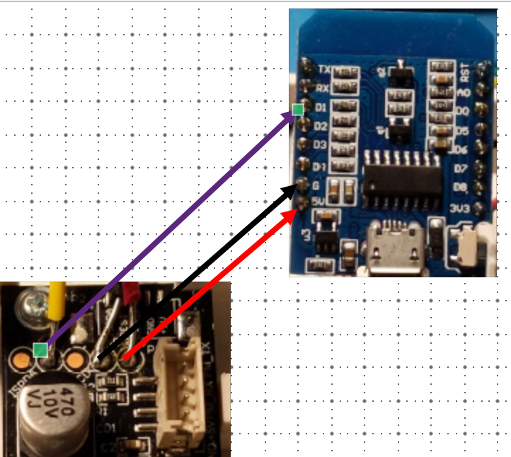
As a quick note, once the firmware is flashed, you'll also need to choose how you're connecting the Ikea sensor to the board, you'll see what I mean on the tutorial video or his write up, but for the level 1 option to add just the ESP8266 board, following where it's being soldered on below, the sensors should look like this:
It's Soldering time!
I did not find the soldering to be particularly difficult, but it is a little bit finicky. I ended up actually buying a new soldering iron, called the Pinecil because I had some old soldering irons that were not very user friendly. And this one is open source. You do not have to spend a lot of money on a soldering iron, and it is also completely possible that either your school or your town has a makerspace where you can go and use a soldering iron. For example, the school that I work at you can actually just go ask one of the computer science or engineering teachers and they will make sure to give you a quick little safety rundown and then you can use one of the many soldering irons that we have if you're a student. What we're going to be doing is actually soldering three wires onto the board that we bought and then the other side of those wires is going to get soldered onto the ikea sensor.NOTE: If nothing else, get a soldering iron with a digital temp reading. The ones that say "High" or "Low" are most common, nothing are just not worth it.
Now on to the ikea sensor, you are going to have to open it up and this is going to require a small screwdriver. If you do not already have a screwdriver of the appropriate size, you can go buy one or you can buy a small hardware kit, like this one for $20, if you think you're going to be doing a lot of projects like this it may be worth getting a nice set of lots of different sizes of screwdrivers, if you're not sure try asking at your school, work, or local library, they may have one that you can borrow.
One of the tips that I will give about soldering is when you are soldering the wires to the board that's in the ikea sensor, consider re-tinning the solder area. What I mean by that is we are not actually going to be soldering a wire into a hole through a board, we are going to be soldering a wire to a board flat. there's this little area that's a connector that we're going to be soldering to, I am not very good at soldering so I found it easier to add some solder to the area and then add the wire.
I ended up using wire that I already had, which was 22 gauge wire, and that seems to work just fine. I ended up keeping to a more traditional color coding scheme, where black was ground, and red was power, and then I just chose a third color for the third wire. Note: Do not cut too much wire! the first time that I tried this I made my wires too long and it made it more difficult to fit the board into the ikea case, I would recommend cutting your wires to be about the same height as the actual ikea air sensor. And the reason that I would recommend having shorter wires is so that it is easier to get the board into the case when you're done.
For me what I found to be the easiest, was to pre-tin the ikea board with some solder and then solder each of the wires onto the ikea board and then match up the wires to where I wanted to solder them to my mini esp8266 board, and what I did was actually strip some extra covering off of the wires. When you're going to be soldering wires you do have to strip some of the covering off, the covering is an insulation and we can't have that. So I stripped a little bit of extra off so that I would be able to have the wires easily pass through the board and make my soldering a little bit faster. Once you have finished soldering you can always clip the wires back so that they fit better and you don't have to worry about them intersecting because these wires are potentially carrying data or power we want to make sure that they aren't touching in any way. After I have completed the soldering and I've completed the firmware we are all ready to go and I can put the ikea sensor back together. The first time that I tried this I was actually very nervous that I did it wrong and it wasn't going to power up, that ended up not being an issue but just know that if you have that same fear you are not alone. After you have everything put back together, plug in the ikea sensor and we can start working on the attaching of the sensor to home automation.
One of the things that I really liked about the tutorial that I followed is that everything seemed to work out of the box without a ton of fiddling. I'm sure there are more efficient ways to do this I'm sure there's a lot more that you can add and changes that you can make. But if you're looking for something to work sort of quickly and easily I have to say that this absolutely was a relatively quick and easy project once I followed these instructions. Flashing the Tasmota firmware with all sensors was not only relatively easy to do through the website it was also already set up to work with the ikea sensor because so many other people have done it.
If you find wiring diagrams to be helpful, you're going to want to solder your wires following this picture to add the ESP8266 mini board to your ikea sensor:
How to add to Home Assistant and Automate things
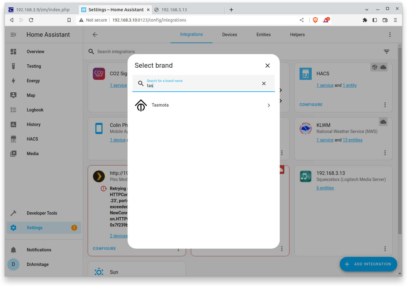
Now that we have the ikea sensor put back together and plugged in to the wall, we should be able to go through the discovery portion so that we can get this attached to our Home Assistant. Now in my case I already had an mqtt server setup, there is also a tutorial for that if you are interested and you don't already have one, one of the things that I really liked about this, is because we entered in our Wi-Fi information during the configuration, it should be automatically discoverable.So what we can actually do is add an integration of the Tasmota, go to your Home assistant, and go to "Settings--> Integrations-->Add Integration" and Search for Tasmota
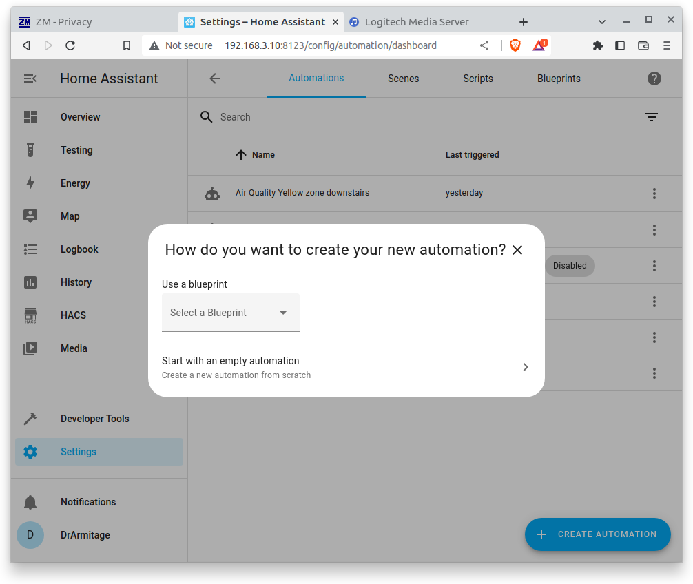
Now that this is all here we can get to the actual automation portion if that's something that you're interested in. One of the things that I ended up trying out was the exact same automation that was shown in his video, which was sending a warning as soon as the air quality dropped into the yellow zone. To do this you'll open your Home Assistant and go to "Settings-->Automations" and then hit the blue button on the lower right that says "Add automation"
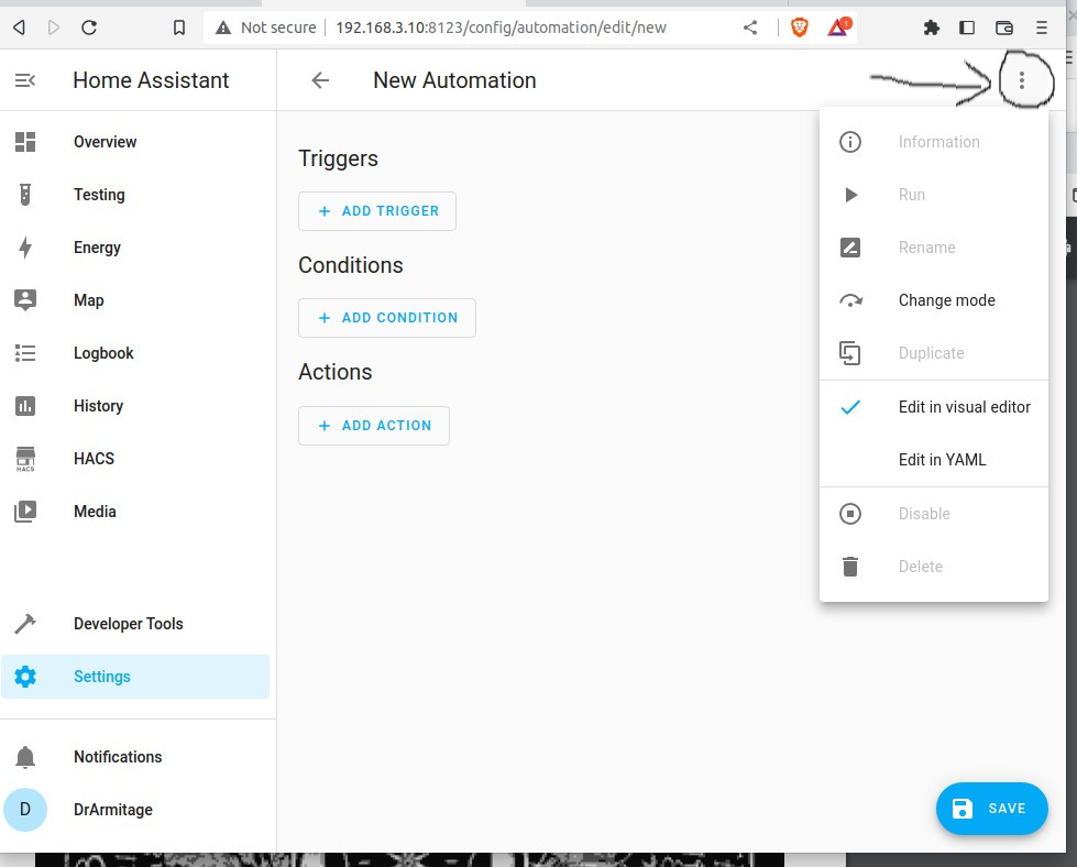
Choose the "Empty Automation" option and then you can start! You can do this using a GUI menu, or the YAML option. To get to the YAML option, click on the three dots on the upper right side next to the "New Automation"
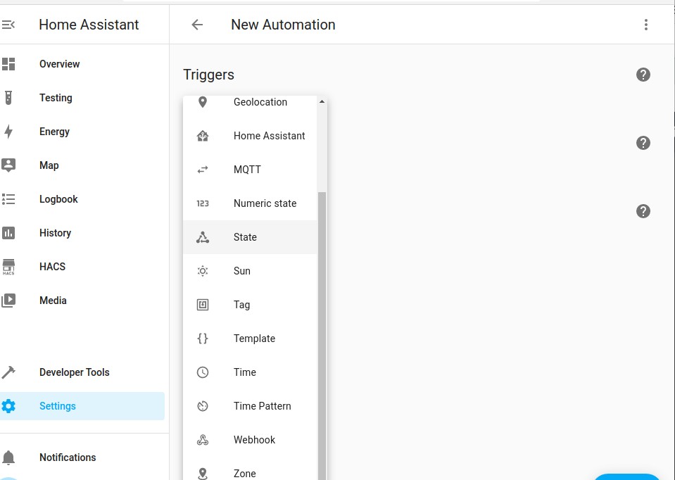
The options can be a bit confusing, but let's take the example of notification when the device isn't working. We'll choose the "Trigger" and then "State", this is like saying when a thing happens, in this case the thing is the state of the device being unavailable. So we'll want to choose "Trigger" Then "State" and then the name of our device, in this case whatever you called it when you added it. This will be just like the video except we're choose "State" instead of a numeric value
Level 2 Upgrade with more sensors!
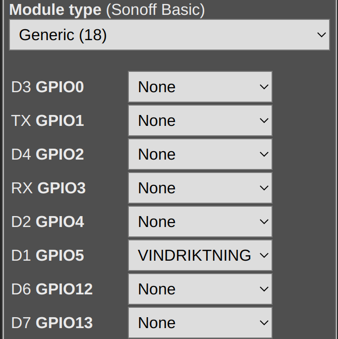
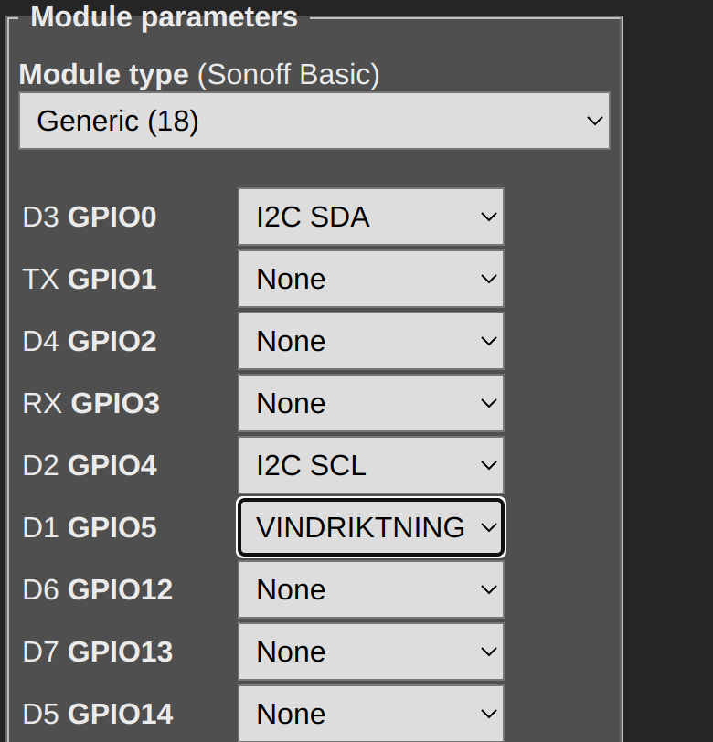
The second level of the project is adding in another sensor to track more data about your air quality. The Ikea sensor can see PM2.5 which is just particles in the air. But there are a wide range of other sensors to track things like temperature, humidity, pressure and VOCs. I choose to add a BME680 (BME680 explained by Adafruit) which tracks all of those, but if you aren't interested in that much data, you could choose a BME280 or BMP280 both of which track less, but are cheaper. More info on the BME280 can be found here from Adafruit There is a video on how to add the BME680 here if you're interested in adding another sensor. There is more soldering involved, and the steps aren't broken down to quite the same level as the other video, so I will call this a Level 2 project if you complete Level 1 (adding wifi) successfully, try out Level 2. The changes you'll need to make are soldering on 4 more wires OR working with the JST connectors. I choose to solder on more wires. You'll also need to add 2 more choices to the module configuration, if you go back to the IP address of your board (likely a 192.168.X.X address) you'll see where you added "Vindriktning" to the D1 option. We're going to make two more changes to this screen, you'll add the I2C SDA to D3 and I2C SCL to D2 as show here:
If you find wiring diagrams to be helpful, you're going to want to solder your wires following this picture to add the ESP8266 mini board to your ikea sensor and the BME680 board:
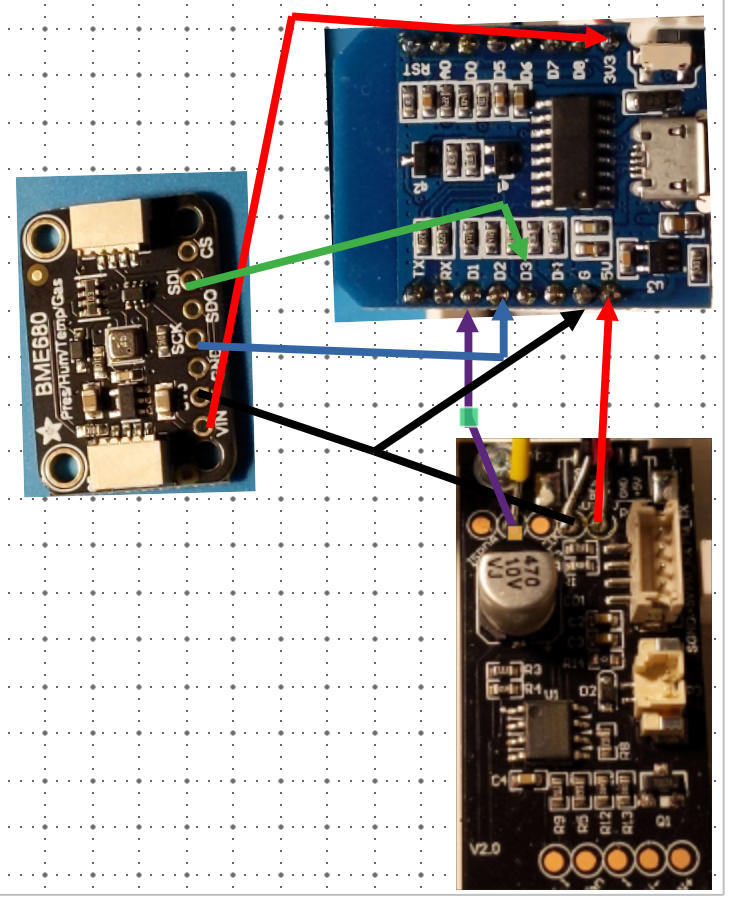
| ESP8266 Mini | BME680 |
|---|---|
| G | GND |
| 3V3 | VIN |
| D2 | SCK |
| D3 | SDI |
Recommended Upgrades
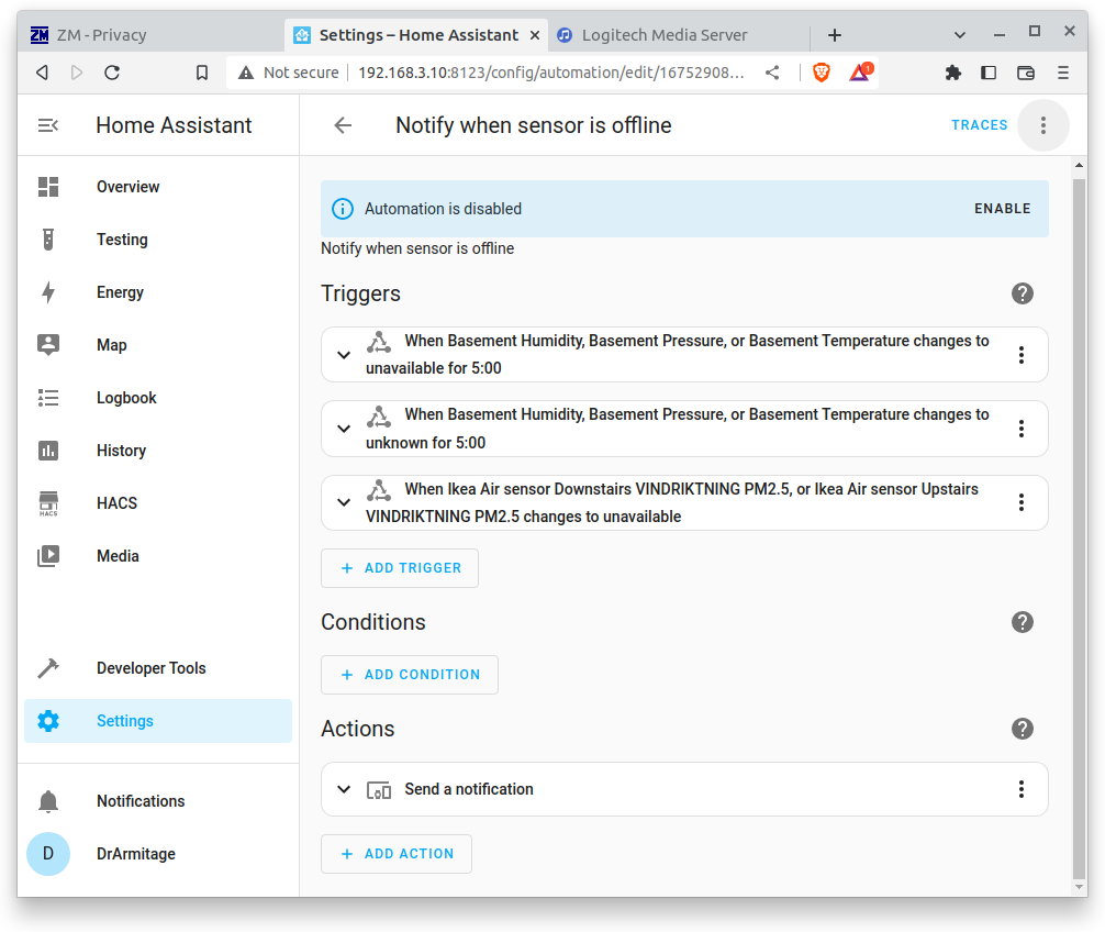
One thing that I would absolutely recommend you trying is automation. If you're going to have an air quality sensor setup, you should try out some of the automation options you can do with the results, things like turning on an air purifier if the quality is too poor, notify you if the quality drops too much, or even things like running this in a less used portion of the house (basement/attic) and seeing what's happening there and how you can make the air quality better. I would recommend setting up an automation so that if the sensor stops working for whatever reason you get notified about it. One of the things that I've noticed having several sensors throughout the house, is one of them can go down and I won't necessarily notice until I'm actually checking it and then I won't know when it went out. I went over how to do that above, but that is a good second automation to try.
Ideas for how to save some Money
There aren't a ton of ways to save money on this project, the air sensor chip alone is likely to run you $10-$15, and you'd still need the cable and housing and everything. I think this project is the cost saving solution for air quality monitoring and is cheaper then the other options I've seen.
Cost breakdown with the supplies I used
| Supply Name | Cost | Weblink |
|---|---|---|
| Ikea Air Quality Monitor | $16 | https://www.ikea.com/us/en/p/vindriktning-air-quality-sensor-60515911/ |
| Ikea Air Quality Monitor Power Supply | $6 | https://www.ikea.com/us/en/p/lillhult-usb-a-to-usb-c-dark-gray-70527602/ |
| ESP8266 mini with Wi-Fi (this is a 5 pack, but you only need one for this project) | $16 | https://a.co/d/cbZEMIk |
| Wires (there will be A LOT of extras) | $10 | https://a.co/d/aPnfibQ |
| Optional: Wire stripper | $14 | https://a.co/d/3EM2XpA |
| Total for one monitor | $25.50 | |
| Total (there will be a LOT of extra wire supplies and 4 extra ESP boards!) | $62 |